A few posts back, I started writing about building a miniature Jumbotron… or Minitron. I have finally managed to get enough of the pieces together to call this thing done. There are still some rough edges, but it is close enough that I am satisfied that I completed what I set out to do and am now ready to move on. 🙂
Quick Background on Minitron
Minitron is a very small scrolling textual display. The project was inspired by something that I saw at the 2016 Embedded Software Conference in Minneapolis. I think that there may be several uses for the project, including not just scrolling text messages, but also possibly displaying things like news headlines, stock ticker symbols, or just about any kind of textual information that you want in semi-realtime. Backing the hardware components is a small app running on Heroku. That app allows users to sign-up, register their own “Minitron”, and define the messages they might want to display on the display. The app allows for up to 12 messages to be predefined for each minitron. The Minitron periodically communicates with the web app running on Heroku to update the message it is displaying. The hardware includes a single push button that allows users to select which message they want to appear on their Minitron.
HardwareFirmware Components
The Minitron hardware consists these basic components:
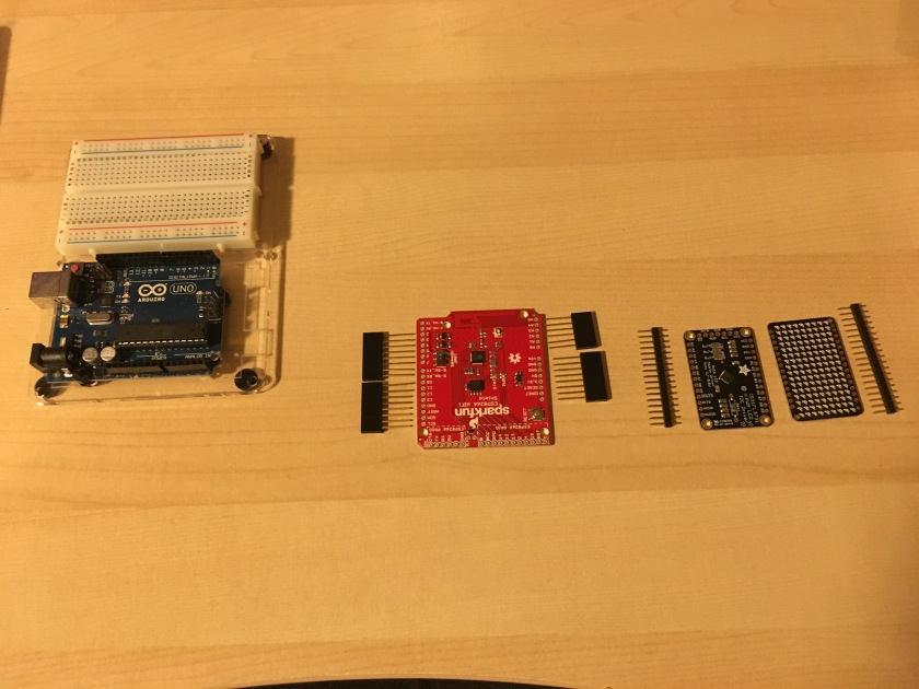
- An Arduino Uno.
- An Adafruit Charlieplex Display (https://www.adafruit.com/product/2947)
- An Adafruit Charlieplex Display driver board (https://www.adafruit.com/product/2946)
- A Sparkfun Arduino ESP8266 WIFI Shield (https://www.sparkfun.com/products/13287)
- A tactile pushbutton (not shown).
- Various hookup wires (not shown).
Smoke Rising from the Bench…
The first step in building the minitron is to solder together all the components. First, solder the backpack onto the charlie-plex display. In order to do this, you should first solder the connectors to the display, and then solder on the backpack. The tricky part of this process is to make sure that the pins are straight. You can use a breadboard to hold the headers as shown below… just be careful not to melt the breadboard.
Once you have the front soldered, I recommend soldering a header on the charlieplex backpack before you solder the backpack to the display. See the image below. This will allow you to plug the display assembly directly into a breadboard, or you can use the header to plug wires in. The later will come in handy if you decide that you want to have the display in a “landscape” orientation vs “portrait”, or if you want to run some wires so that you can position the display in a different location.
Once the headers have been soldered to the chaliexplex display, solder the backpack onto the back. Make sure that you can read the printing on the back. In other words, pin 1 on the display should match up with pin A1 on the driver board, and pin 9 on the display should match up with pin B9 on the driver board. The finished display and driver board with the header should look like this:
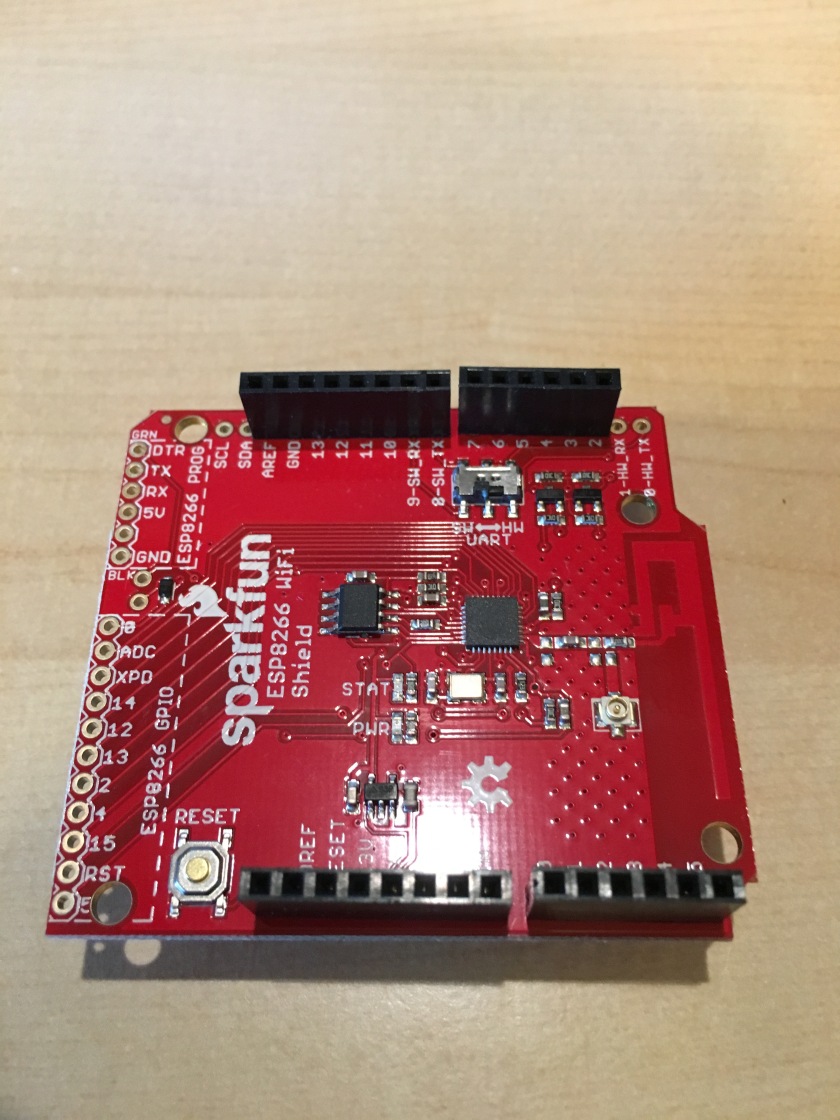
Now that we have the display ready to go, we need to assemble the Sparkfun ESP8266 Wifi shield. This consists of soldering on the headers to the shield. When soldering the headers on, make sure that the female end is pointing up, and that on the digital side, you leave the RX, TX (two left most pins with the silkscreen oriented up) and the SDA and SCL pins open. See below:
Once the WiFi shield is complete, attach it to the Arduino, and then wire as shown below.

NOTE: THE SPARKFUN ESP8266 WIFI ARDUINO SHIELD IS NOT PICTURED. Simply plug the shield into the Uno as you would expect. The headers are exactly the same. Also, note that the Charlieplex daughter board (https://www.digikey.com/catalog/en/partgroup/is31fl3731-adafruit-16×9-charlieplexed-pwm-led-matrix-driver/59819?WT.srch=1&gclid=CPSi9Pvj_NMCFR62wAodANoMkQ) is shown, but not the actual display. That needs to be assembled and plugged into the driver as described above.
Software Components

To understand the software involved with the Minitron, let’s start with a basic user workflow.
- A user logs into the Minitron administrative app via a browser (minitron.herokuapp.com)
- After registering, the user registers a device name on the site. Once the name has been successfully recorded, a device code is returned to the user. This code is then used in the Arduino program (sketch) that will run on the users Minitron.
- The user is able to use their browser and the Arduino web app to program 12 different messages (0-11), that they will want to display on their minitron.
- The user programs their minitron Arduino using the program provided in the GIT repository, and fills in the SSID and password of their Wifi network, along with the device code they obtained from the website.
- Once programming is complete, the minitron makes a call back to an endpoint in the web application that includes the device code and a message number. The server responds with a message that the minitron then displays.
- If the user wishes to change the message displayed on the minitron, they simply hold down the button on the minitron. The minitron checks to see if the button is being pressed every three times it displays a message. If the button is down, the minitron starts to display the number 0-12 in sequence. When the user sees the number of the message they want to be displayed, they let up on the button.
There are two basic pieces of software involved with this system: the Minitron Arduino program, and the web application running on Heroku. Both are stored in the Minitron GIT repo.
https://github.com/fractalbass/minitron
Arduino Code:
The Arduino code, which is in the GIT repo above will need to be flashed onto the Arduino. In order to do that, you will need the Arduino IDE. There is a web-based tool for Arduino. I have not used it, so cannot comment on it either way. You will need to have the ESP8266 Shield libraries and the Adafruit Charlieplex Driver library installed in the Arduino IDE. You can find information about those on the links at the beginning of this article for those products.
You will need to make some modifications to the code before you upload it to your Arduino. Those modifications include setting your wireless SSID and Password, as well as the device code for your minitron. Refer to the workflow described for more information on the device code. You will need to should register your Minitron first on the web app before program the Arduino. Registering the Minitron with the web app will generate a device code that you need for the programming step. Below are the lines that you will need to modify in the Arduino program.
...
// Replace SSID and PWD with the appropriate values for
// your WiFi network.
const char mySSID[] = "PUT_YOUR_SSID_HERE";
const char myPSK[] = "PUT_YOUR_NETWORK_PASSWORD_HERE";

// Replace DEVICE_CODE with your device code.
const char deviceCode[] = "PUT_YOUR_DEVICE_CODE_HERE";
...
Web Application Code:
The web application code is included in the GIT repo mentioned above. If you simply want to build your own Minitron, you don’t need to worry about it. The app is up and running on Heroku and available for you to use… at least until too many people start to hit it and I need to start paying for the app. If that happens, I would be surprised. That said, my plan is simply to email folks that have registered devices, and ask them to make a donation to help pay for the next level of Heroku.
The web app is written in Groovy/Springboot. It involves a very basic Postgres database. I tried to test drive the app… that said I developed it solo. Without a pair to keep me honest, I am afraid that there may be some holes where I didn’t do a good job of test driving things. Feel free, if you would like, to fork the app and make a pull request for any changes/enhancements.
One thing you may notice in the app is that I have included a docker image that can be used to bring up the underlying Postgres database for integration testing. Please check out my recent blog post https://pragmaticiot.wordpress.com/2017/03/05/springboot-integration-testing-with-dependencies-running-in-docker/ for more information on that subject. Credit should go to Thom Dieterich for teaching me a ton about using docker in this fashion. (As well as for teaching me tons of stuff about groovy, pairing, and XP in general.) Though I didn’t work with him on this project, his ideas and practices have heavily influenced the web server portion of Minitron.
Thom is a wizard dev, and I had the great pleasure of working with him at Bluestem Brands and PeopleNet over the past couple of years. Thanks, Thom.
The code for the Minitron application is free to whoever wishes to use it. Please feel free to download/clone/fork the repo. All I ask is that you give credit (or blame) when referencing the code or app… and you consider offering me (and Thom) a super high paying gig at some point in the future. 🙂
Conclusion:
There are several interesting things that I learned while working on this project. They include:
- The Sparkfun ESP8266 Wifi Shield is a great way to used ESP8266 with your Arduino projects. I tried, initially, to use an Adafruit FeatherIO board, and a separate ESP8266. While the FeatherIO board worked great with the charlie plex displays, using it with the ESP8266 was a pain. In general, I have not had much luck with the raw ESP8266 devices. The Sparkfun Shield, however, was a dream to work with.
- This app demonstrates:
- Test driven development.
- Programming a RESTful API with SpringBoot and Groovy.
- Docker (see my previous post.)
- Arduino development, and some basic Arduino circuit design
- Basic electrical component assembly.
- This app DOES NOT DO JUSTICE TO SECURITY. There are a number of shortcomings to this project in terms of security. User passwords are encrypted in the database, however, messages to and from the server are not. This is a major problem, and as a result, this application should NOT BE USED for any kind of medical, financial, or any use case, unless the security issues are addressed. Specifically:
- Messages should be encrypted.
- Arduino code should be required to provide additional authentication information, rather than just a device code.
- The web application should be modified to be
I hope you enjoyed this post and will consider building your own Minitron!!!